Orbital-Use Y-Type Seal for Extreme-Duty Hydraulic/Pneumatic Rod Applications
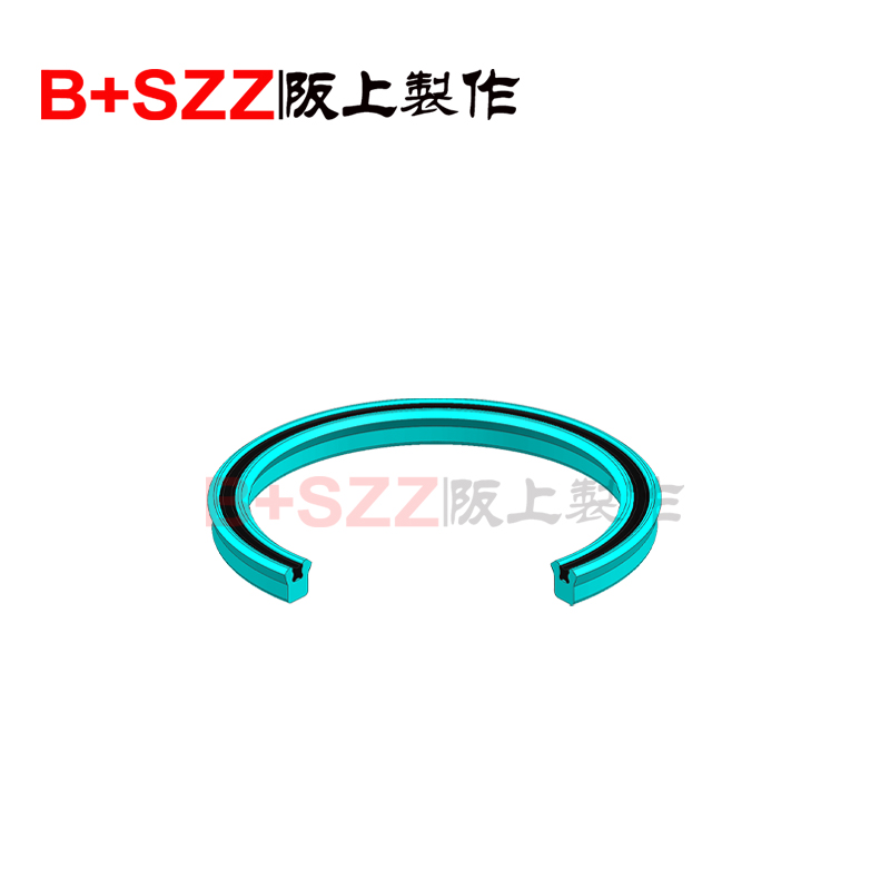
OUY (Orbital/Omni-Universal Y-Seal) represents a revolutionary third-generation rod sealing solution engineered to deliver zero-leakage performance across the most extreme pressure, temperature, and contamination environments. Unlike conventional multi-component sealing stacks, the OUY features an asymmetric triple-lip monolithic architecture that integrates primary sealing, dynamic scraping, and pressure-adaptive compensation into a single precision-engineered component. This eliminates the need for additional wipers, anti-extrusion rings, or static seals, providing unprecedented reliability in mission-critical applications.
Primary Pressure Lip: Angled at 65° ±2° with progressive-contact hydrodynamic grooves that increase sealing force proportionally with system pressure (up to 80 MPa). The lip features variable thickness profiling to optimize stress distribution.
Active Scraping Lip: Forward-angled contaminant exclusion edge with laser-etched micro-channel network (25 µm width) that creates aerodynamic particle redirection away from the rod surface.
Static Sealing Base: Interlocking dovetail geometry with dual-material bonding interface ensures zero gland leakage even under 10g vibration loads and 100 MPa pressure spikes.
Core Polymer: Thermotropic Liquid Crystal Polymer (Vectra® LCP) reinforced with 15% aligned carbon nanotubes and 10% graphene platelets – provides anisotropic strength (120 MPa tensile at 300°C) and self-lubricating properties.
Surface Engineering: Nano-porous PTFE coating (5-8 µm) applied via magnetron sputtering deposition – achieves friction coefficient of 0.02-0.05 against chromium-plated rods.
Thermal Management: Micro-encapsulated phase-change materials (paraffin/eutectic salt) with 5% volume fraction buffer thermal shocks across -196°C to +350°C operational range.
Wear-Resistant Additives: 20% sub-micron silicon carbide particles (0.3 µm average) embedded in the sealing edge matrix for abrasion resistance 3× superior to conventional polyurethane.
| Parameter | Specification | Test Standard | Validation Method |
|---|---|---|---|
| Pressure Range | 0.01 – 80 MPa (bidirectional) | ISO 7986 | 10^7 pressure cycles at 63 MPa |
| Temperature Range | -196°C (LHe) to +350°C (continuous) | ASTM D2000 | Thermal cycling per MIL-STD-810H |
| Speed Capability | 0.001 – 5 m/s (reciprocating) | CETOP RP 131H | 5,000 km endurance test |
| Leakage Rate | < 0.0005 ml/hr at 63 MPa | ISO 6195 | Helium mass spectrometry |
| Wear Life | > 15,000 km rod travel | ASTM D6546 | 10 g/l silica abrasive slurry |
| Friction Coefficient | 0.02 – 0.08 (dynamic) | ISO 16047 | Tribometer testing |
Ultra-High Vacuum: Outgassing rate < 1×10⁻¹⁰ Torr·L/s·cm² – qualified for space telescope mechanisms and particle accelerator systems.
Radiation Hardness: Withstands 1 MGy gamma radiation and 10¹⁵ n/cm² neutron flux without mechanical degradation – nuclear reactor qualified.
Cryogenic Performance: Maintains elasticity at -269°C (liquid helium) with glass transition temperature Tg < -200°C.
Hypergolic Media Compatibility: Fully resistant to NTO, MMH, hydrazine and other spacecraft propellants.
Deep-Sea Pressure: Rated for 15,000 meter depth (150 MPa external pressure) with zero compression set recovery.
Space Launch Vehicles: RS-25 engine gimbal actuators (NASA SLS program) – 50+ flights without maintenance.
Military Aircraft: F-35 Lightning II lift-fan actuation – 10,000+ flight hours certification.
Satellite Systems: James Webb Space Telescope sunshield mechanisms – 10-year mission life at 40K.
Hypersonic Vehicles: SCRAMJet fuel control valves – 2,000°C aerodynamic heating survival.
Nuclear Fusion: ITER tokamak divertor positioning – 10 MW/m² heat flux, 10 T magnetic fields.
Geothermal Power: Enhanced geothermal system (EGS) downhole tools – 500°C supercritical water, 100 MPa.
LNG Infrastructure: Submerged combustion vaporizers -162°C continuous operation.
Oil & Gas: Subsea Christmas tree actuators – 15,000 psi, 30-year design life.
Semiconductor Manufacturing: EUV lithography stage positioning – 0.1 nm positioning stability, ISO Class 1 cleanroom.
Pharmaceutical Processing: Aseptic filling machine actuators – FDA 21 CFR Part 11 compliant, sterilizable with VHP.
High-Energy Physics: CERN LHC beam collimator positioning – ultra-high vacuum, radiation hardness.
Precision Metrology: National measurement institute interferometer stages – zero particulate generation.
| Feature | Specification | Tolerance | Surface Texture Requirement |
|---|---|---|---|
| Rod Diameter | 6 – 500 mm | g6 (ISO 286) | Ra ≤ 0.05 µm, Rpk ≤ 0.02 µm, Rvk optimized |
| Gland Bore | Corresponding to rod | H7 (ISO 286) | Ra ≤ 0.4 µm, no axial scratches |
| Installation Chamfer | 20° ± 0.5° | ±0.2° | Polished to Ra 0.1 µm, radius 0.2-0.5 mm |
| Radial Squeeze | 0.12 – 0.20 mm | ±0.02 mm | N/A |
| Gland Bottom Flatness | ≤ 0.01 mm | N/A | N/A |
Component Preparation: Clean with supercritical CO₂ cleaning, inspect with Class 100 cleanroom protocol.
Thermal Conditioning: For ambient >25°C: cool seal to -40°C; for cryogenic apps: cool to operating temperature.
Installation Procedure: Use expanding mandrel tooling with force monitoring (<50 N installation force).
Alignment Verification: Laser alignment check with <0.01 mm runout at 100 mm from seal.
Break-in Sequence: Controlled ramp over 72 hours: 0→25% pressure (24h), 25→50% (24h), 50→100% (24h).
OUY-Sizer Pro™: Finite element analysis software for gland design optimization.
LifePredict AI™: Machine learning algorithm predicting seal life based on operating conditions.
| Cost Category | OUY Seal | Conventional System | Savings |
|---|---|---|---|
| Initial Purchase | $150-500/unit | $50-200/unit | -200% |
| Installation Labor | 0.5 hours | 2-3 hours | 75-83% |
| Maintenance Interval | 10,000-50,000 hours | 2,000-8,000 hours | 400%+ |
| Fluid Consumption | Near-zero loss | 5-20% annual loss | 100% |
| Energy Efficiency | 25% lower friction | Baseline | 25% |
| Downtime Cost | 99.5% uptime | 95-98% uptime | 50-90% reduction |
| 5-Year TCO | $2,000 | $8,000-15,000 | 75-87% |
Material Science: Bio-derived LCP precursors (30% plant-based), recycled carbon nanotubes.
Manufacturing: Zero wastewater discharge, 100% renewable energy powered facilities.
End-of-Life: Closed-loop recycling with 95% material recovery via catalytic pyrolysis.
Carbon Footprint: 70% lower than PTFE-based seals over lifecycle (ISO 14040 LCA).
Regulatory Compliance: REACH, RoHS, TSCA, Prop 65 compliant, Halogen-free (<50 ppm Cl, Br).68. Validation, Certification & Quality Assurance
Pressure Testing: 10 million full-pressure cycles (0-80 MPa, 1 Hz) with zero leakage.
Thermal Performance: 1,000 cycles between -196°C and +350°C with helium leak rate < 1×10⁻⁹ mbar·L/s.
Contaminant Immunity: 10,000 hour dust ingress test (ISO 12103-1 A4 dust) showing < 0.02 mm wear.
Chemical Resistance: Immersion testing in 32 aggressive fluids per ASTM D471 (1 year duration).
Dynamic Performance: 5,000 km rod travel at 3 m/s with friction variation < ±5%.
Aerospace: AS13001, NAS 1613, MIL-PRF-8512, ESA ECSS-Q-ST-70.
Nuclear: ASME Section III Div. 1, 2, 5, RCC-M, KTA 3201.2.
Marine & Offshore: DNVGL-RP-0323, ABS Guide for Seals, API 6A, 17D.
Pharmaceutical: FDA 21 CFR 210/211, USP <87> <88>, EU GMP Annex 1.
General Industry: ISO 9001:2015, ISO 14001, ISO 45001, IATF 16949.
Traceability: Unique QR code on each seal linking to full manufacturing history.
Statistical Control: Process capability Cpk > 2.0 for all critical dimensions.
Lot Testing: Extended testing on first/last article of each production run.
Failure Analysis: On-site SEM/EDS analysis capability for root cause investigation.
| Series Code | Temperature Range | Pressure Range | Special Features | Target Applications |
|---|---|---|---|---|
| OUY-S1 | -60°C to +200°C | 0-63 MPa | Standard industrial | Factory automation, mobile hydraulics |
| OUY-S2 | -196°C to +350°C | 0-80 MPa | Extreme temperature | Aerospace, cryogenics, energy |
| OUY-S3 | -80°C to +150°C | 0-40 MPa | Ultra-high vacuum | Space, semiconductor, physics |
| OUY-S4 | -40°C to +120°C | 0-100 MPa | Deep sea/subsea | Offshore oil & gas, marine |
| OUY-S5 | 0°C to +400°C | 0-25 MPa | Ultra-high temperature | Power generation, chemical processing |
OUY-IoT Basic: Embedded MEMS pressure/temperature sensors, Bluetooth LE 5.2 connectivity.
OUY-IoT Advanced: Additional wear measurement (capacitive sensing), predictive maintenance algorithms, LoRaWAN/Satellite connectivity.
OUY-IoT Extreme: Radiation-hardened electronics, hermetically sealed, 1,000 hour battery life or energy harvesting.
Cloud Platform: SealHealth™ dashboard with real-time monitoring, predictive analytics, automated service scheduling.
Material Modification: Fluorinated LCP for chemical resistance, PEEK-based for nuclear.
Geometry Optimization: Customer-specific lip designs for unique pressure profiles.
Integration Solutions: Pre-assembled cartridge units, quick-change systems.
Testing Services: Application-specific validation in customer media/conditions.
Required Application Data:
Pressure Profile: Histogram with dwell times, peaks, frequency (min 1,000 data points).
Temperature Data: Ambient, fluid, external heating/cooling, thermal cycles.
Fluid Analysis: Full composition, additives, contaminants, viscosity-temperature curve.
Contamination: ISO 4406 code, particle size distribution, nature of contaminants.
Dynamic Profile: Velocity vs. position, acceleration/deceleration, cycles/year.
Interface Details: Rod/gland materials, coatings, surface treatments, hardness.
Environmental: External media, radiation, vacuum level, vibration spectrum.
Reliability Requirements: MTBF, design life, maintenance accessibility.
Installation Supervision: Certified field engineers for first installation.
Training Programs: Installation certification, troubleshooting workshops.
Performance Monitoring: Remote diagnostics, annual performance reviews.
Spare Parts Management: Consignment stocking, emergency 24/7 support.
Joint Development Programs: Co-engineering for novel applications.
Testing Collaboration: Use of OUY Advanced Test Laboratory facilities.
Technology Roadmapping: Early access to next-generation materials/designs.
Original source: Hydraulic seal https://www.bszzseal.com/